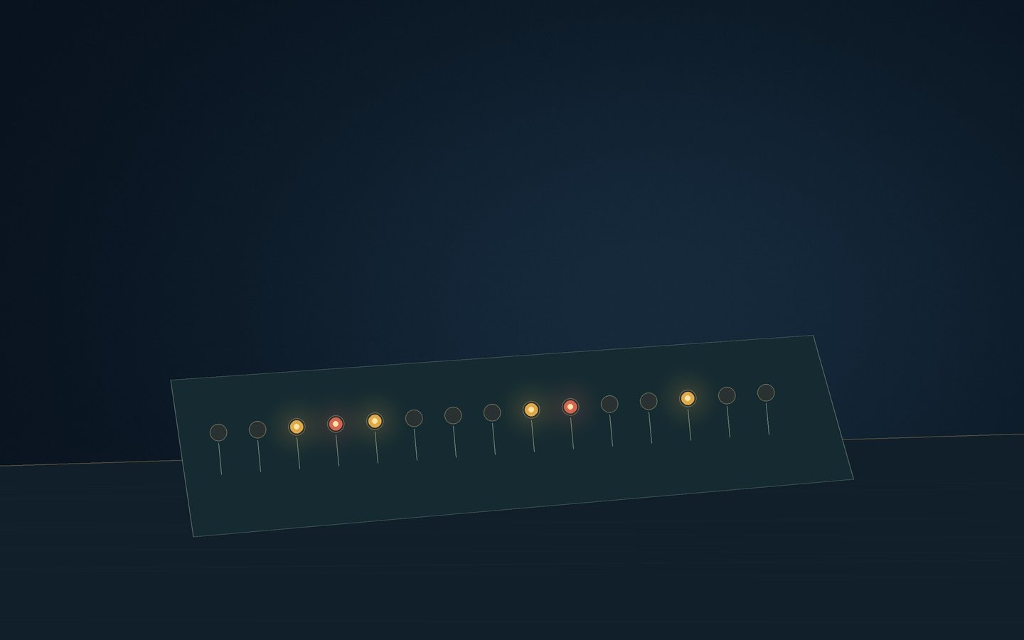
A flashing LED array makes time visible inside the image being tested. The camera films a known pattern of light changes while the recording system assigns timestamps to its frames. Comparing the pattern in the saved images with those timestamps tests the relationship between the recorded time and the actual light-gathering interval. This reaches a different question from checking whether a clock display agrees with another clock.
The array is a timing reference expressed as light. Its pattern needs a documented schedule and a justified relationship to the external time source. Without that information, a row of blinking LEDs is an interesting subject but not a timing measurement. The observer must be able to explain what a lit element means at a particular point in the sequence.
Why LEDs suit a visible marker
Wikipedia's article on light-emitting diodes notes their fast switching compared with incandescent light sources. A deliberately controlled light change can therefore provide a useful visible timing marker. The complete arrangement still includes the controller, reference connection and camera response. Fast switching by the component does not remove uncertainty elsewhere in the test.
A pattern can advance along the row or use another documented arrangement that distinguishes successive timing states. The test depends on knowing that arrangement, not on a particular layout. Keep the elements separable in the camera image and avoid brightness that spreads across them. If adjacent lights blend together, the recorded pattern becomes harder to read reliably.
A GPS receiver can supply the external marker. Wikipedia's discussion of the PPS signal explains that the pulse identifies a boundary but needs accompanying information to establish the full time. An array controller must join those roles correctly. Retain reference-status information as well as the visible sequence so that an orderly pattern is not mistaken for verified absolute time.
Put the actual recording chain under test
Use the camera mode, interface, recorder and file format intended for observing. Set the exposure deliberately and preserve the unprocessed recording. A test made through a different display path or with a convenient temporary setting does not establish the behaviour of the event recording. The central advantage of the light pattern is that it passes through the same imaging path as the star.
Position the array so the lights are clear and the relevant sensor region is known. With a rolling shutter, different parts of the image can describe different exposure moments. A pattern filmed near an image edge may not establish the timing at a star located elsewhere. Camera shutter choices explains why sensor position and readout mode belong in the test notes.
Disable automatic exposure or brightness adjustments when their operation would make the pattern uncertain and when the equipment permits deliberate control. Check that dim and bright states remain distinguishable without saturation. The purpose is to locate light changes within exposures, rather than to produce a dramatic-looking photograph of the array.
Read exposure start and duration
Each recorded image contains the light states that overlapped its exposure. Compare those states with the documented schedule. Elements that were on throughout an interval can appear clearly lit; a change partway through an exposure can leave a partial contribution. The combination can bracket exposure start and end, provided the pattern and response are understood.
Do not treat the brightness of a partially lit element as an exact fraction of an exposure without checking the response. Camera gamma, illumination differences and background can alter the recorded level. In many cases, an unambiguous bracket is more defensible than a finely calculated instant derived from uncertain brightness. Keep unclear cases in the notes rather than resolving them by appearance alone.
Compare the resulting exposure interval with the timestamp definition. Does the label refer to its beginning, end or another stated point? Hardware timers distinguishes triggers, exposure signals and attached time labels. The LED evidence can help establish which relationship the assembled system actually preserves.
Look between exposures as well
Follow the light pattern across successive images. A gap between the end of a usable exposure and the beginning of the next is dead time. A brightness change occurring there cannot be measured directly by the camera, even if the saved frame labels are perfectly regular. Describe the gap when it affects the uncertainty assigned to an event boundary.
Repeated images and missing frames also deserve inspection. Determine whether repetition belongs to the camera's integration mode or to the recorder's behaviour. Check frame identifiers, light states and timestamps together. A mismatch can reveal that times and images became separated even though the file still plays smoothly.
Wikipedia identifies UTC as the reference standard used to regulate clocks and time. State whether the array's schedule and the recorder's labels refer to that same standard. Matching names are necessary context, but the visible test is what examines their practical relationship in this configuration.
Keep the trial file, array schedule, reference status and camera settings together. Repeat the relevant check after a mode or recording-path change, and include start-up behaviour when it matters. The page on judging time quality places such evidence in a wider comparison method. A successful test supports a stated configuration and uncertainty; it should remain available for later inspection alongside the observation.